
Price
495.00
4599.00
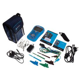


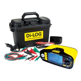

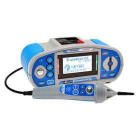

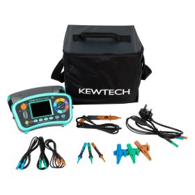
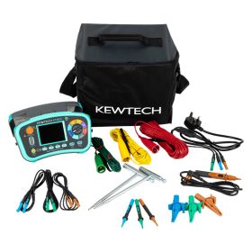
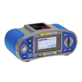
Multifunction testers, known commonly as MFTs or installation testers, are combination electrical testers that can be used to carry out all types of electrical testing procedures to verify and maintain electrical installations.
Similar to multimeters in terms of functionality, multifunction testers expand upon the common multimeter by carrying out testing across a much wider spectrum and also include unique testing procedures that you won't find on common DMMs. Since they can carry out multiple tests without the need to constantly switch the tester you're using, multifunction testers are an extremely common sight inside electricians' equipment. Without the hassle of constantly switching equipment to perform tests, electricians can stay in line with 18th-edition rules and regulations while carrying out their test procedures in a timely and efficient manner.
The most common testing procedures that multifunction testers can carry out include:
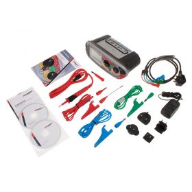
Not all MFTs can carry out all of these functions - it is important to make sure you get the right instrument for your needs, so make sure you check which testing procedures the multifunction tester you're looking at can perform before investing.
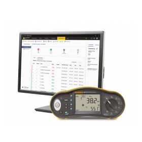
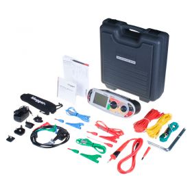
Multifunction testers are also commonly divided up into two categories - downloadable, and non-downloadable. Downloadable multifunction testers are designed with internal memory, allowing users to store test data, communicate this data to a PC and interact with it further using software packages. Non-downloadable MFTs are generally cheaper as they include no internal memory structure, and are designed for simple testing with users jotting down results gained.