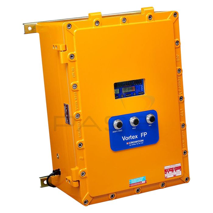
Crowcon Vortex FP Exd Flameproof Control System VX-FP - Choice of Model

- All relays are continuously monitored
- Vortex PC software
- Water and dust resistant to IP66
These Crowcon Vortex FP are ATEX-certified Exd Flameproof gas detector control panels for use in Zone 1 or Zone 2 hazardous areas such as on offshore production platforms or within refineries. They offer all of the standard Vortex features, as well as a display fitted with magnetic switches which enable the system to be interrogated or inhibited without opening the system enclosure.
The Vortex flameproof (FP) systems are designed for use in ATEX Zones 1 & 2, with IP66 ingress protection, Unlike many other flameproof systems, all day-to-day operations can be undertaken without opening the enclosure, removing the need for hot work permits.
With up to 24 relays, the enclosure is capable of accommodating up to 4 intrinsically safe (I.S.) barriers for interfacing with I.S. detectors and alarms.
Simple to Use
- All the day-to-day operations can be completed via push buttons on the front panel - removing the requirement for hot-work permits to complete everyday tasks
- Fault and alarm LEDs on the front panel - providing an instant indication of system status
- Alarm and channel settings can be adjusted at the panel
Highly Flexible
- Uses Vortex PC software - customisation is easy and user-friendly
- Uses industry-standard Modbus RTU (or optionally Profibus) communications links - simple to integrate with PLC, DCS, or SCADA control systems
Robust and Reliable
- Water and dust resistant to IP66
- All relays are monitored continuously - ensuring full functionality
Product Range
- Crowcon C011184 Vortex FP Exd Flameproof Control System VX-FP 4/0 - 4 Input Channels, No Relay Modules
- Crowcon C011185 Vortex FP Exd Flameproof Control System VX-FP 8/0 - 8 Input Channels, No Relay Modules
- Crowcon C011186 Vortex FP Exd Flameproof Control System VX-FP 12/0 - 12 Input Channels, No Relay Modules
- Crowcon C011187 Vortex FP Exd Flameproof Control System VX-FP 4/1 - 4 Input Channels, 1 Relay Module
- Crowcon C011188 Vortex FP Exd Flameproof Control System VX-FP 8/1 - 8 Input Channels, 1 Relay Module
- Crowcon C011189 Vortex FP Exd Flameproof Control System VX-FP 12/1 - 12 Input Channels, 1 Relay Module
- Crowcon C011190 Vortex FP Exd Flameproof Control System VX-FP 4/2 - 4 Input Channels, 2 Relay Modules
- Crowcon C011191 Vortex FP Exd Flameproof Control System VX-FP 8/2 - 8 Input Channels, 2 Relay Modules
- Crowcon C011192 Vortex FP Exd Flameproof Control System VX-FP 12/2 - 12 Input Channels, 2 Relay Modules
- Crowcon C011193 Vortex FP Exd Flameproof Control System VX-FP 4/3 - 4 Input Channels, 3 Relay Modules
- Crowcon C011194 Vortex FP Exd Flameproof Control System VX-FP 8/3 - 8 Input Channels, 3 Relay Modules
- Crowcon C011195 Vortex FP Exd Flameproof Control System VX-FP 12/3 - 12 Input Channels, 3 Relay Modules
- Crowcon C011196 Vortex FP Exd Flameproof Control System VX-FP 4/4 - 4 Input Channels, 4 Relay Modules
- Crowcon C011197 Vortex FP Exd Flameproof Control System VX-FP 12/3 - 8 Input Channels, 4 Relay Modules
Call 01642 931 329 or complete the form:
| Vortex FP | ||
|---|---|---|
| Size | 440 x 640 x 332mm (17.3 x 25 x 13 ins) |
|
| Weight | 70Kgs (154lbs) approx. | |
| Enclosure Material | LM25 aluminium with polyester powder coating | |
| Ingress Protection | IP66 | |
| Channels | Up to 12 (1 to 3 4-way input modules) | |
| Operating Temperature | -10°C to +40°C (14°F to +140°F) | |
| Humidity | 0-95% RH non-condensing | |
| Inputs | Gas | 2 or 3 wire 4-20mA (sink or source), 0-5V |
| Fire - Smoke & Heat Detectors, Manual Call-points | Up to 3 loops, Up to 20 devices per loop | |
| Outputs | External Audible Visual Alarm Drive | Via relays, four 24Vdc 0.5A supplies provided |
| Relays | Type | Up to 32 SPCO with bus extension module |
| Assignment - Common | Battery back-up is not available | |
| Assignment - Voting | Alarms, faults, and system events | |
| Relay Modes | Energised/de-energised, latched/non-latched, time-delayed, pulsed | |
| Digital Communications | DCS/PLC/PC | RS-485 Modbus or Profibus |
| Local Configuration Link | RS-232 (configuration software and lead supplied) | |
| Logging | Up to 300 alarm, power, fault, system events are stored in Non-Volatile Memory | |
| Panel Indication | Channel Number | 2-digit 7-segment Green LED |
| Gas Reading | 4-digit 7-segment Red LED | |
| Measurement Units | % LEL, ppm, % Vol, Fire | |
| Power | Green LED | |
| Battery OK | Green LED | |
| Run/hold Indication | Green LED | |
| Channel Test Mode | Flashing Amber LED | |
| System Fault - Integrity Watchdog | Amber LED | |
| Displayed information can be altered and outputs can be inhibited during calibration using a magnetic key | ||
| Alarm Indication | Audible - Internal Sounder | Piezo |
| Visual - Alarm | Level 1 & 2, Red LED | |
| Visual - Fault | Per channel, Amber LED | |
| Visual - Inhibit | Per zone, Amber LED | |
| Power | AC Mains | 110 or 240Vac 3.2A max 150W PSU 20 - 30Vdc |
| Battery Back-up | Battery back-up not available | |
| Approvals | Low Voltage Directive | EN61010-1 |
| EMC | Directive 2014/30/EU: EN50270, FCC: CFR47 Part 15, IECES-003 | |
| ATEX | TEX Ex II 2G D Zone 1, Zone 2, IECEx optional | |
| Functional Safety | Validated to IEC61508 | |


