| Input Power |
100 to 240 V (± 10 %) AC, 1 Ø, 50/60 Hz, 700 VA |
| Outputs |
All outputs are independent of sudden changes in line voltage and frequency. This provides stable outputs not affected by sudden changes in the main source. All outputs are regulated so changes in load impedance do not affect the output. |
| Output Current |
Output power ratings are specified in AC RMS values and peak power ratings.
| Output Current |
Power |
Max V |
| 50 mA2 |
5 VA |
10.0 V RMS |
| 1 A |
15 VA |
15.0 V RMS |
| 4 A |
200 VA (282 peak) |
50.0 V RMS |
| 15 A |
200 VA (282 peak) |
13.4 V RMS |
| 32 A |
200 VA (282 peak) |
6.67 V RMS |
| 60 A |
319 VA (450 peak) |
5.00 V RMS 90 Cycles |
| DC 200 Watts |
| Duty cycle: |
32 A Continuous, 60 A for ± 1.5 seconds |
|
| Current Amplifier - Extended Power Range |
The SMRT current amplifier provides a unique flat power curve from 4 to 32 A to permit testing of electromechanical high-impedance relays, and other high-burden applications, with an extended operating range of up to 60 A at 319 VA RMS. |
| AC Low-level Rogowski Output (Converted Current Channels) |
Each current channel can provide the following voltage outputs with the following Ranges:
| Output Volts |
Max I |
| 0 - 2 VRMS |
10 mA |
| 0 - 10 VRMS |
100 mA |
| 0 - 40 VRMS |
25 mA |
| Duty cycle: |
Continuous |
|
| AC Voltage Output |
Outputs are rated with the following ranges:
| Output Current |
Power |
Max I |
| 2 V |
0.02 VA |
10 mA |
| 30 V |
150 VA |
5 A |
| 150 V |
150 VA (282 peak) |
Variable |
| 300 V |
150 VA (282 peak) |
0.5 A |
| DC 150 Watts |
| Duty cycle: |
Continuous |
|
| “PowerV™” Voltage Amplifier - Extended Power Range |
The SMRT voltage amplifier provides a flat power curve from 30 to 150 V in the 150 V range to permit testing of high current applications such as panel testing. |
| Voltage Amplifier in Current Mode |
The voltage amplifier is convertible to a second current source with the following output capability. Output power ratings are specified in RMS values and peak power ratings.
| Output Current |
Power |
Max V |
| 5 A |
150 VA (212 peak) |
30.0 V RMS |
| 15 A |
120 VA |
8.0 V RMS |
| Duty cycle: |
5 A Continuous, 15 A for ± 1.5 1.5 seconds |
|
| Phase Angle |
| Ranges: |
0.00 to 359.99 degrees, counterclockwise, or clockwise rotation, or 0.00 to ± 180.00 degrees |
| Accuracy: |
± 0.02° typical, ± 0.25° max at 50/60 Hz |
|
| Frequency |
The output modules provide a variable frequency output with the following ranges and accuracy:
| Ranges: |
DC: 0.001 to 1000.000 Hz
Output amplifiers can provide transient signals with a range of DC to 10 kHz for transient playback using IEEE-C37.111 Standard COMTRADE files. |
| Resolution: |
0.001 Hz |
| Frequency accuracy: |
2.5 ppm typical
25 ppm, 0° to 50° C, at 50/60 Hz maximum
AC/DC AUX: 250 ppm, 50/60 Hz maximum |
|
| Total Harmonic Distortion |
Less than 0.1 % typical, 2 % maximum at 50/60 Hz |
| Timer |
The timer-monitor input is designed to monitor and time-tag inputs, as a ‘sequence of events’ recorder. In addition, the binary input controls enable the user to perform logic AND/OR functions and conditionally control the binary output relay to simulate circuit breaker, trip, reclose, and carrier control operations in real-time. The timer function displays in seconds or cycles, with the following range and resolution:
| Seconds: |
0.0001 to 99999.9 (auto-ranging) |
| Cycles: |
0.01 to 99999.9 (auto-ranging) |
| Accuracy: |
± 0.001 % of reading, typical
± 2 least significant digit
± 0.005 % of reading from 0 to 50 °C maximum |
|
| Binary Input - Start/Stop/Monitor Gate |
To monitor the operation of relay contacts or trip SCR, a continuity light is provided for the input gate. Upon sensing continuity, the lamp will glow. In addition to serving as wet/dry contacts the binary inputs may be programmed to trigger binary output sequence(s).
| Input rating: |
Up to 300 V AC/DC |
|
| Binary Output Relays |
SMRT1 has an independent, galvanically isolated, output relay contact to accurately simulate relay or power system inputs to completely test relays removed from the power system. The binary output simulates normally open/normally closed contacts for testing breaker failure schemes. The binary output can be configured to change state based on binary input logic.
| AC rating: |
400 V max., Imax: 8 A
2000 VA max. breaking capacity |
| DC rating: |
300 V max., Imax: 8 A, 80 W |
| Response time: |
< 10 ms |
|
| Metering |
Measured output quantities such as AC Amperes, AC Volts, DC Volts, or DC Amperes, and time may be simultaneously displayed on the large, colour TFT LCD touch screen of the STVI. The AC and DC outputs display the approximate voltage/current output before the initiation of the outputs. Accuracies are specified from 10 to 100 % of range, 25 °C ± 5 °C, 50-60 Hz. |
| AC Voltage Amplitude |
| Accuracy: |
± 0.05 % reading + 0.02 % range typical
± 0.15 % reading + 0.05 % range maximum |
| Resolution: |
0.01 |
| Measurements: |
AC RMS |
| Ranges: |
30, 150, 300 V |
|
| AC Low-level Voltage Output |
| Range: |
2 V |
| Accuracy: |
0 - 1 V: 0.5 mV typical and 1 mV guaranteed
1 - 2 V: 0.5 mV typical and 2 mV guaranteed |
| Resolution: |
0.001 |
| Measurements: |
AC RMS |
|
| AC Low-level Rogowski Output (Converted Current Channels) |
| Range: |
2 V |
| Accuracy: |
0 - 1 V: 0.5 mV typical and 1 mV guaranteed
1 - 2 V: 0.5 mV typical and 2 mV guaranteed |
| Resolution: |
0.001 |
| Measurements: |
AC RMS |
| Ranges: |
10, 40 V |
| Accuracy: |
± 0.05 % of reading + 0.02 % of range typical
± 0.15 % of reading + 0.05 % of range guaranteed |
| Resolution: |
0.001 |
| Measurements: |
AC RMS |
|
| AC Current Amplitude |
| Accuracy: |
± 0.05 % reading + 0.02 % range typical
± 0.15 % reading + 0.05 % range maximum |
| Resolution: |
0.001/0.01 |
| Measurements: |
AC RMS |
| Ranges: |
32, 60 A |
|
| AC Low Current |
| Range: |
50 mA |
| Accuracy: |
± 0.5 mA typical and 1 mA guaranteed |
| Resolution: |
0.0001 |
| Measurements: |
AC RMS |
|
| DC Voltage Amplitude |
| Accuracy: |
0.1 % range typical, 0.25 % range maximum |
| Resolution: |
0.01 |
| Measurements: |
RMS |
| Ranges: |
30, 150, 300 V |
|
| DC Current Amplitude |
| Accuracy: |
± 0.05 % reading + 0.02 % range typical
± 0.15 % reading + 0.05 % range maximum |
| Resolution: |
0.001/0.01 |
| Measurements: |
RMS |
| Range: |
30 A |
|
| Convertible Source in AC Current Mode |
| Accuracy: |
± 0.05 % reading + 0.02 % range typical
± 0.15 % reading + 0.05 % range or ± 12.5 mA whichever is greater |
| Resolution: |
0.001 |
| Measurements: |
AC RMS |
| Ranges: |
5, 15 A |
|
| Temperature Range |
| Operating: |
32 to 122 °F (0 to 50 °C) |
| Storage: |
-13 to 158 °F (- 25 to 70 °C) |
| Relative Humidity: |
5 - 90 % RH, Non-condensing |
|
| Unit Enclosure |
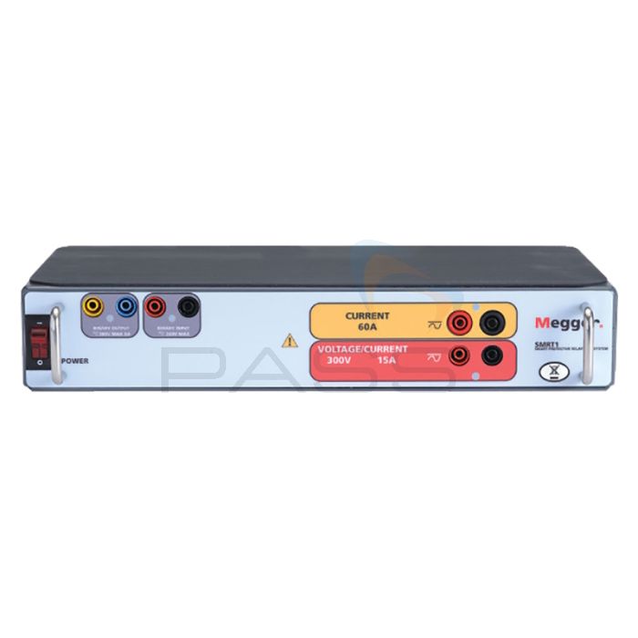
The SMRT1 unit comes housed in a rugged, metal, lightweight enclosure. IEC Enclosure Rating IP20. An optional enclosure for a 19-inch rack mount is available.
The rack mount enclosure includes two BNC connectors on the back panel. These connectors are used to amplify an external analogue signal using the SMRT amplifiers. Application of ± 10 Volts peak will provide full-scale output from the selected output. |
| Dimensions |
| Standard enclosure (SMRT1): |
13.5W x 2.4H x 6.75D in. (34.3W x 6.1H x 17.2D cm) |
| Rack mount enclosure (SMRT1): |
19W x 3.5H x 8.75D in. (48.3W x 8.9H x 22.2D cm) |
|
| Weight |
| Standard enclosure (SMRT1): |
8.9 lb. (4 kg) |
| Rack mount enclosure (SMRT1): |
10.85 lb. (4.9 kg) |
|
| Conformance Standards |
| Safety: |
EN 61010-1 |
| Shock: |
EN/IEC 60068-2-27 |
| Vibration: |
EN/IEC 60068-2-6 |
| Transit drop: |
ISTA 1A |
| Free fall: |
EN/IEC 60068-2-32 |
| Drop/topple: |
EN/IEC 60068-2-31 |
|
| Electromagnetic Compatibility |
| Emissions: |
EN 61326-2-1, EN 61000-3-2/3
FCC Subpart B of Part 15 Class A |
| Immunity: |
EN 61000-4-2/3/4/5/6/8/11 |
|
| Protection |
Voltage outputs are protected from short circuits and thermally protected against prolonged overloads. Current outputs are protected against open circuits and thermally protected against prolonged overloads. |
| Communication Interfaces |
Ethernet (2)
Bluetooth (optional) |


