
Voltage, Current & Loop Calibrators
Specific instruments for calibrating voltage, current and loop. Many of the instruments in this section are multifunctional, and can calibrate more than one parameter. Includes portable calibrators and bench-top calibrators ideal for laboratories.
Find out more about Voltage, Current & Loop Calibrators below.
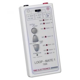
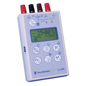
- 7 set calibration points
- 0.1% accuracy
- 0 to 10 V or 4 to 20mA loop
- Simulate various signal types
- Multiple outputs
- High accuracy
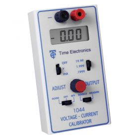
- High accuracy of 0.05%
- Can measure and source current and voltage
- Portable with its own carrying case
- Works with current and voltage levels
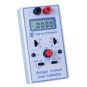
- Accuracy of 0.02%
- Suitable for being used by a number of professions
- Accuracy of 0.02%
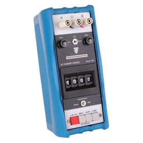
- 1V with up to 3 ranges
- Protection against short circuit and overload
- Ranges are fully programmable
- Easy and simple to use – even for first timers
- Min/Max Recording
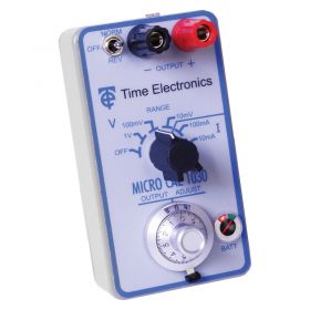
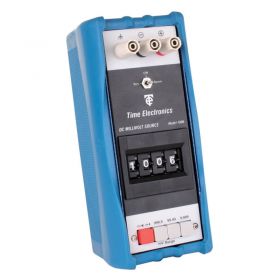
- 3 ranges: 0 to 1V, 0 to 100mV and 0 to 10mV
- High accuracy
- Microvolt null balance display
- 2.4 watts max output power
- Three separate output ranges
- Useful for lots of different applications
- Easy operation and LCD screen for measurement referencing
- Three modes to choose from
- Comes with free rubber protective case for fieldwork and travelling
- Accuracy of 0.02%
- Fitted safety terminals
- Choose battery or mains power supply
- Can be used in numerous situations
- Compatible with different types of plugs
- Incredible accuracy of 0.02%
- Tilt stand can be adjusted to suit you
- Powered by rechargeable battery or mains plug
- Five ranges of DC voltage
About Voltage, Current & Loop Calibrators
Also known as current loops, 4-20mA sources are one of the most common methods used in the process industry for transmitting data between sensors and the applications that control and monitor them. The main advantage of a current loop is it can be combined with a huge variety of different sensors to measure temperature, pressure, liquid flow, or light. This data is then compatible with a wide range of different management applications that interoperate with the data and react accordingly.
4-20mA current loops work by taking the results from the sensor and converting it to a proportional current. This means that a zero result causes a 4mA to be transmitted and a 20mA current is sent when the sensor is at full capacity. This information is then sent through copper cables to a receiver at the controller. The controller then decodes the sent signal into the format that is required by the process monitoring application.
The drawback with this method is that over long distances the signal can eventually erode as the voltage begins to wane. An engineer must also be careful when laying these cables to ensure that no electrically noisy systems are located close by, otherwise, they can affect the signal. The main precaution that can be taken is to ensure the use of shielded cabling but this can become too expensive if used over long distances.
To ensure that a current loop is operating effectively engineers often use current calibrators to test the cables and ensure that there are no issues that need resolving no matter what their source.